


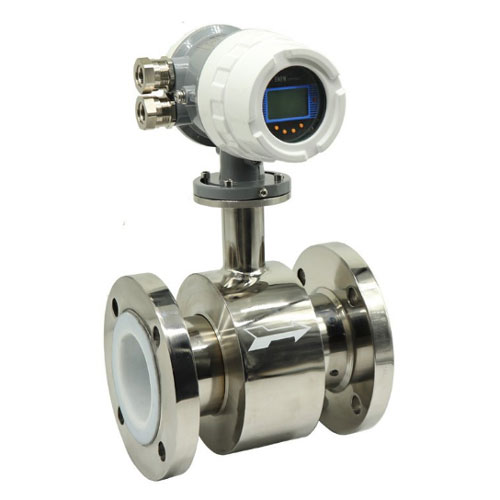
EFM series flow measurement sensor
The measurement principle of EFM-EM series intelligent electromagnetic flowmeter is based on Faraday's law of electromagnetic induction. The measuring tube of the flowmeter is a non-magnetic alloy short tube lined with insulating material. Two electrodes are fixed on the measuring tube by passing through the tube wall along the diameter direction. The electrode tip is basically flush with the inner surface of the lining. When the excitation coil is excited by two pulse waves, a working magnetic field with a magnetic flux density of B will be generated in the direction perpendicular to the axis of the measuring tube. At this point, if a fluid with a certain conductivity flows through the measuring tube. Induce electromotive force E by cutting magnetic field lines. The electromotive force E is proportional to the magnetic flux density B, measured as the product of the inner diameter d of the tube and the average flow velocity v. The electromotive force E (flow signal) is detected by the electrode and sent to the converter through a cable. After amplifying and processing the flow signal, the converter can display the fluid flow rate and output signals such as pulses and analog currents for flow control and regulation.E=KBdv:E -- represents the signal voltage (v) between the electrodes
B -- Magnetic flux density (T)
d -- Measure the inner diameter of the tube (m)
v -- Average flow velocity (m/s)
In the formula, k, D is a constant, and since the excitation current is constant, B is also a constant. Therefore, from E=KBdv, it can be seen that the volume flow rate Q is proportional to the signal voltage E -, that is, the signal voltage E induced by the flow rate is linearly related to the volume Q. Therefore, as long as E is measured, the flow rate Q can be determined, which is the basic working principle of electromagnetic flow meters.
According to E=KBdv, parameters such as temperature, density, pressure, conductivity, and liquid-solid composition ratio of the measured flow medium will not affect the measurement results. As for the flow state, as long as it conforms to axisymmetric flow (such as laminar or turbulent flow), it will not affect the measurement results. Therefore, electromagnetic flowmeter is a true volumetric flowmeter. For manufacturers and users, the volumetric flow rate of any other conductive fluid medium can be measured without any correction as long as it is calibrated with ordinary water. This is a prominent advantage of electromagnetic flow meters, which is not found in any other flow meter. There are no active or obstructed components inside the measuring tube, so there is almost no pressure loss and high reliability.
Product features:
² Measurement is not affected by changes in fluid density, viscosity, temperature, pressure, and conductivity;
² There are no obstructing flow components or pressure loss inside the measuring tube, and the requirements for straight pipe sections are relatively low;
² Series nominal diameter DN15~DN3000. There are multiple options for sensor lining and electrode materials;
² The converter adopts a novel excitation method, with low power consumption, stable zero point, and high accuracy. The flow range can reach 1500:1;
² The converter can be integrated or separated from the sensor;
² The converter adopts a 16 bit high-performance microprocessor, 2x16 LCD display, convenient parameter setting, and reliable programming;
² The flowmeter is a bidirectional measurement system, equipped with three integrators: forward total, reverse total, and differential total; Can display positive and negative flow rates, and has multiple outputs: current, pulse, digital communication HART;
² The converter adopts surface mount technology (SMT) and has self checking and self diagnostic functions.
Technical data of the whole machine and sensors: | |||||
Nominal diameter | 15、20、25、32、40、50、65、80、100、125、150、200、250、300、350、400、450、500、600、700、800、900、1000、1200、1400、1600、1800、2000、2200、2400、2600、2800、3000 | ||||
Maximum flow rate | 15m/s | ||||
Accuracy | DNl5~DN600 | ±0.3%(flow rate≥1m/s);±3mm/s(flow rate <1m/s) | |||
DN700—DN3000 | ±0.5%(flow rate≥0.8m/S);±4mm/s(flow rate <0.8m/S) | ||||
Fluid conductivity | ≥5uS/cm | ||||
Nominal pressure | 4.0MPa | 1.6MPa | 1.0MPa | 0.6MPa | 6.4、10MPa |
DNl5~DN150 | DNl5~DN600 | DN200~DN1000 | DN700~DN3000 | Special order | |
Environmental temperature | sensor | —25℃~十60℃ | |||
Converter and integrated type | —10℃~十60℃ | ||||
Lining materials | Polytetrafluoroethylene, chloroprene rubber, polyurethane, perfluoroalkoxy (F46), and mesh PFA | ||||
Maximum fluid temperature - body type | Integrated type | 70℃ | |||
Separate type | Chloroprene rubber lining | 80℃;120℃(specify when ordering) | |||
Polyurethane lining | 80℃ | ||||
PTFE lining | 100℃;150℃(specify when ordering) | ||||
Perfluoroethylene propylene (F46) | |||||
mesh PFA | |||||
Signal and ground electrode materials | Stainless steel 0Crl8Nil2M02Ti, Hastelloy C, Hastelloy B, titanium, tantalum, platinum/iridium alloy, and stainless steel coated with tungsten carbide | ||||
Electrode scraper mechanism | DN300~DN3000 | ||||
Connecting flange material | Connecting flange material carbon steel | ||||
Grounding flange material | Grounding flange material stainless steel 1Cr18Ni9Ti | ||||
Imported protective flange material | DN65~DNl50 | Stainless steel 1Crl8Ni9T | |||
DN200~DNl600 | Carbon steel and stainless steel 1Crl8Ni9Ti | ||||
Polyurethane lined sensor | DNl5~DN3000 separated rubber or polyurethane lined sensor | IP65或IP68 | |||
Other sensors, Integrated type flow meters, and separate converters IP6 | IP65 | ||||
Spacing(separation type) | Converter and the sensor is generally not more than 100m | ||||
The measurement principle of EFM-EM series intelligent electromagnetic flowmeter is based on Faraday's law of electromagnetic induction. The measuring tube of the flowmeter is a non-magnetic alloy short tube lined with insulating material. Two electrodes are fixed on the measuring tube by passing through the tube wall along the diameter direction. The electrode tip is basically flush with the inner surface of the lining. When the excitation coil is excited by two pulse waves, a working magnetic field with a magnetic flux density of B will be generated in the direction perpendicular to the axis of the measuring tube. At this point, if a fluid with a certain conductivity flows through the measuring tube. Induce electromotive force E by cutting magnetic field lines. The electromotive force E is proportional to the magnetic flux density B, measured as the product of the inner diameter d of the tube and the average flow velocity v. The electromotive force E (flow signal) is detected by the electrode and sent to the converter through a cable. After amplifying and processing the flow signal, the converter can display the fluid flow rate and output signals such as pulses and analog currents for flow control and regulation.
E=KBdv:E -- represents the signal voltage (v) between the electrodes
B -- Magnetic flux density (T)
d -- Measure the inner diameter of the tube (m)
v -- Average flow velocity (m/s)
In the formula, k, D is a constant, and since the excitation current is constant, B is also a constant. Therefore, from E=KBdv, it can be seen that the volume flow rate Q is proportional to the signal voltage E -, that is, the signal voltage E induced by the flow rate is linearly related to the volume Q. Therefore, as long as E is measured, the flow rate Q can be determined, which is the basic working principle of electromagnetic flow meters.
According to E=KBdv, parameters such as temperature, density, pressure, conductivity, and liquid-solid composition ratio of the measured flow medium will not affect the measurement results. As for the flow state, as long as it conforms to axisymmetric flow (such as laminar or turbulent flow), it will not affect the measurement results. Therefore, electromagnetic flowmeter is a true volumetric flowmeter. For manufacturers and users, the volumetric flow rate of any other conductive fluid medium can be measured without any correction as long as it is calibrated with ordinary water. This is a prominent advantage of electromagnetic flow meters, which is not found in any other flow meter. There are no active or obstructed components inside the measuring tube, so there is almost no pressure loss and high reliability.
Product features:
² Measurement is not affected by changes in fluid density, viscosity, temperature, pressure, and conductivity;
² There are no obstructing flow components or pressure loss inside the measuring tube, and the requirements for straight pipe sections are relatively low;
² Series nominal diameter DN15~DN3000. There are multiple options for sensor lining and electrode materials;
² The converter adopts a novel excitation method, with low power consumption, stable zero point, and high accuracy. The flow range can reach 1500:1;
² The converter can be integrated or separated from the sensor;
² The converter adopts a 16 bit high-performance microprocessor, 2x16 LCD display, convenient parameter setting, and reliable programming;
² The flowmeter is a bidirectional measurement system, equipped with three integrators: forward total, reverse total, and differential total; Can display positive and negative flow rates, and has multiple outputs: current, pulse, digital communication HART;
² The converter adopts surface mount technology (SMT) and has self checking and self diagnostic functions.
Technical data of the whole machine and sensors: | |||||
Nominal diameter | 15、20、25、32、40、50、65、80、100、125、150、200、250、300、350、400、450、500、600、700、800、900、1000、1200、1400、1600、1800、2000、2200、2400、2600、2800、3000 | ||||
Maximum flow rate | 15m/s | ||||
Accuracy | DNl5~DN600 | ±0.3%(flow rate≥1m/s);±3mm/s(flow rate <1m/s) | |||
DN700—DN3000 | ±0.5%(flow rate≥0.8m/S);±4mm/s(flow rate <0.8m/S) | ||||
Fluid conductivity | ≥5uS/cm | ||||
Nominal pressure | 4.0MPa | 1.6MPa | 1.0MPa | 0.6MPa | 6.4、10MPa |
DNl5~DN150 | DNl5~DN600 | DN200~DN1000 | DN700~DN3000 | Special order | |
Environmental temperature | sensor | —25℃~十60℃ | |||
Converter and integrated type | —10℃~十60℃ | ||||
Lining materials | Polytetrafluoroethylene, chloroprene rubber, polyurethane, perfluoroalkoxy (F46), and mesh PFA | ||||
Maximum fluid temperature - body type | Integrated type | 70℃ | |||
Separate type | Chloroprene rubber lining | 80℃;120℃(specify when ordering) | |||
Polyurethane lining | 80℃ | ||||
PTFE lining | 100℃;150℃(specify when ordering) | ||||
Perfluoroethylene propylene (F46) | |||||
mesh PFA | |||||
Signal and ground electrode materials | Stainless steel 0Crl8Nil2M02Ti, Hastelloy C, Hastelloy B, titanium, tantalum, platinum/iridium alloy, and stainless steel coated with tungsten carbide | ||||
Electrode scraper mechanism | DN300~DN3000 | ||||
Connecting flange material | Connecting flange material carbon steel | ||||
Grounding flange material | Grounding flange material stainless steel 1Cr18Ni9Ti | ||||
Imported protective flange material | DN65~DNl50 | Stainless steel 1Crl8Ni9T | |||
DN200~DNl600 | Carbon steel and stainless steel 1Crl8Ni9Ti | ||||
Polyurethane lined sensor | DNl5~DN3000 separated rubber or polyurethane lined sensor | IP65或IP68 | |||
Other sensors, Integrated type flow meters, and separate converters IP6 | IP65 | ||||
Spacing(separation type) | Converter and the sensor is generally not more than 100m | ||||